Counting and displaying RPM
This page contains the information on all activities related to counting and displaying the number of revolutions per minute.
05/30/2015: First Prototype
The idea for his first prototype was that we would have some sort of device that would generate a square pulse for each engine revolution. By measuring the time between two pulses (the t in figure 1 below) we could easily compute the number of revolutions per minutes (RPM).

Inspired by a robotic lab at high school where he had to measure the length of a pulse in order to evaluate the distance measured by a HC-SR04 sonar, Étienne wrote an Arduino
sketch for measuring the time between two pulses, convert it to RPM, and display it on a LCD. The code for this sketch is shown in figure 2.
#include
In order to test the RPM counting sketch, Étienne wrote a second sketch for generating pulses at specific frequencies. The code for this sketch is shown in figure 3.
void setup()
{
  pinMode(3,OUTPUT);
}

int rpm = 2000;
unsigned long gap = 60000/rpm;

void loop()
{
  digitalWrite(3,LOW);
  delay(gap);
  digitalWrite(3,HIGH);
  delay(1);
}
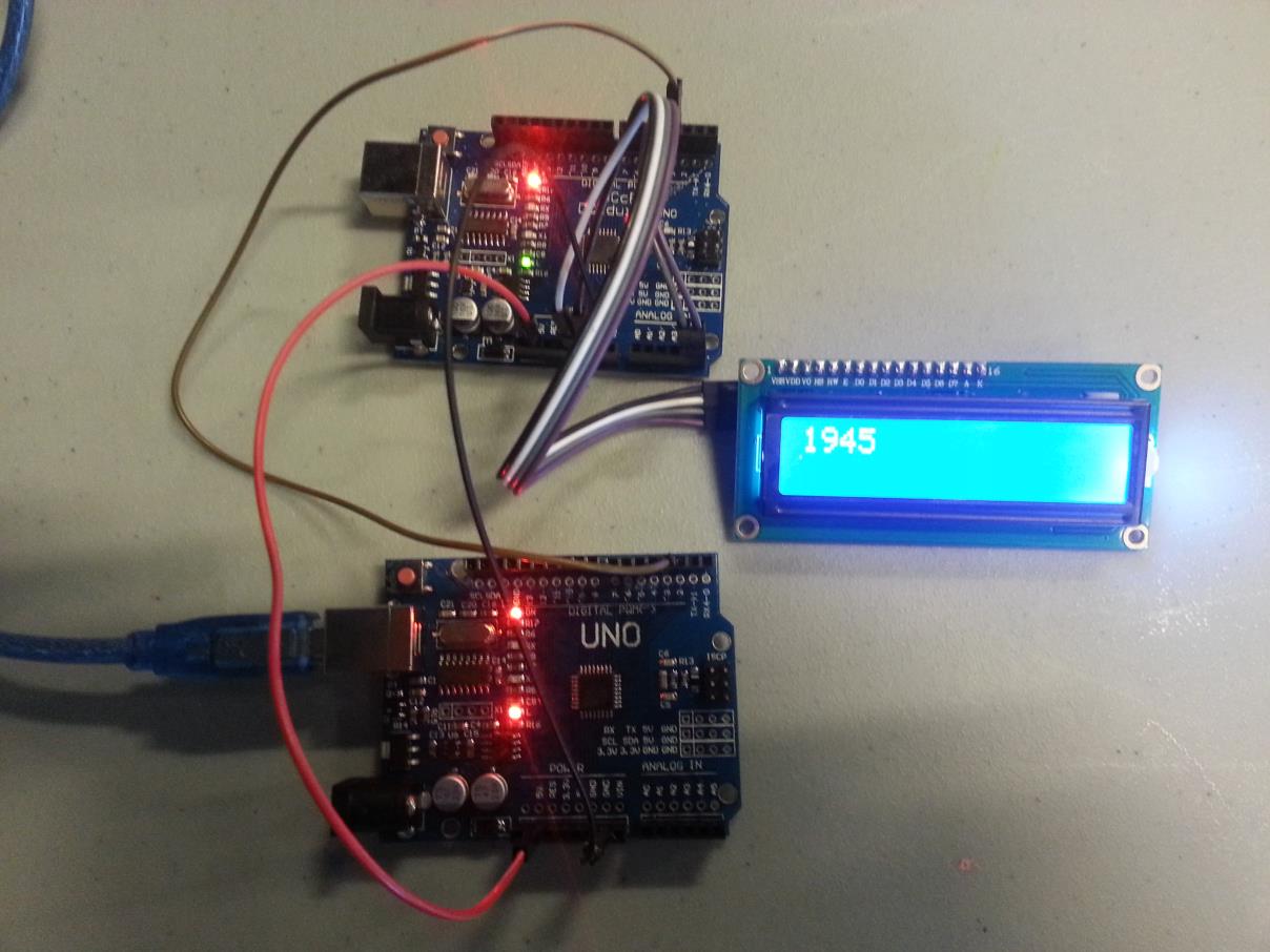
The figure 4 shows two Arduinos running the two sketches. The Arduino connected to a PC with a USB cable is the pulse generator. The Arduino connected to the display is the one that measure the elapsed time between two pulses and convert that to RPM.

Using the PC, Étienne ran the generator at different frequencies (by modifying the rpm variable in the sketch) and he notices that the displayed RPM was not exactly matching the frequency of the generator. This is due to the timing of some instructions that is not accounted for. We will fix that at a later time.
06/20/2015: Using a 3.3v Arduino
We used a 3.3v Arduino mini pro instead of the original 5v Arduino, and we added a 5v to 3.3v level converter between the Arduino and the LCD. We are running the same code as in the original prototype. Nothing else was changed.

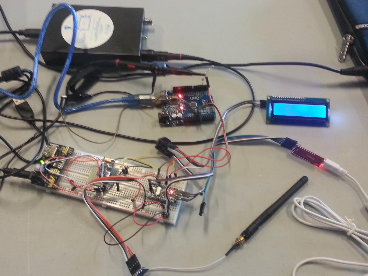
The top Arduino Uno (in blue) is running the pulse generator sketch. The 3.3v Arduino mini pro (with the red led on the bread board) is running the RPM counting sketch. The cable attached to the LCD is leading to the level converter in the middle of the screen.
06/27/2015: Count pulses and compute RPM with interrupt
This week, we modified the code to use an ISR (interrupt service routine) to count the RPM. In this version of the code, we use the pin 8 to receive pulses from the engine. Here is a brief description of the code is working:
- In the last two statements of the Setup function, we specify to call an ISR on interrupt 0 every time pin 8 changes state.
- After the setup, the function ISR(PCINT0_vect) is called every time the state of the pin 8 changes from 0 to 1, or from 1 to 0.
- The code in the function increment the variable pulseCount when the state of the pin changes from 0 to 1.
- The code also get the current time in microseconds when the state of the pin changes from 0 to 1.
- The function ISR(PCINT0_vect) holds the time in microseconds of the last 16 pulses (changes from 0 to 1). To determine the RPM, instead of using the elapsed time for the last pulse, we used the elapsed time for the last 16 pulses. This is used to smooth out the RPM value.
- The current RPM value is saved in a global variable named rpm.
- The function getRPM is used to get the RPM value from the global variable. Because the value is stored in an non-atomic type for the Arduino (many CPU instructions are needed to modify or read it), the getRPM function has to disable the interrupts (cli) before reading it. Without the cli statement, we could read the first part of the value, then the ISR could change the value, and after that we could read the last part of the value. This would lead to getting the wrong value.
The complete code could be found in the figure 6 below.
#include
07/11/2015: Pulse generator using a timer
This week, we modified the code of the pulse generator hoping to gain some accuracy. The pulse generator is used to simulate engine pulses for testing the RPM counter module. In this version of the code, we use used a timer and an ISR (interrupt service routine) that is called every time the timer's counter reaches its maximum value. Here is a brief description of how the code is working:
- The setupTimer function initializes the timer to generate an interrupt every timeInUS micro seconds. The function also attaches the function timerISR to the timer's interrupt.
- The setRPM function transforms the given RPM value into a period time in microseconds, and calls setupTimer.
- The timerISR function generates a pulse. It set the pin 3 to high for one millisecond.
- The loop function reads an RPM value from the serial port and changes the timer to generate pulses for the given RPM value.
The complete code could be found in the figure 7 below.
#include "TimerOne.h"

int defaultRPM = 2000;

void setupTimer(unsigned long timeInUs)
{
  Timer1.initialize(timeInUs);       // Initialize timer1, and set a timeInUs micro second period.
  Timer1.attachInterrupt(timerISR);  // Attaches timerISR() as a timer overflow interrupt.
}

void setRPM(int RPM)
{
  unsigned long timeInUs = 60000000 / RPM;
  setupTimer(timeInUs);
  Serial.println(timeInUs);
}

void timerISR()
{
  sei();
  digitalWrite(3, HIGH);
  delay(1); // Stay high for 1 ms.
  digitalWrite(3, LOW);
}

void setup()
{
  pinMode(3, OUTPUT);
  Serial.begin(9600);
  setRPM(defaultRPM);
}

void loop()
{
  // Read a new RPM value.
  String line = Serial.readStringUntil('\n');
  int RPM = line.toInt();

  if (line != "") {
   if (RPM == 0) {
    Serial.println("error");
   } else {
    Serial.print("setting RPM to ");
    Serial.println(RPM);

    // Set timer to generate pulses corresponding to the given RPM.
    setRPM(RPM);
   }
  }
}
When we first checked the output pulse on an oscilloscope we found that the pulse duration in millisecond was not exactly what was expected.
After adding some debugging code for checking the time in microseconds needed to generate 1000 pulses, we found a match between the expected time in microseconds measured by the Arduino and the expected duration of the pulses. This was suggesting that the code is ok and the problem lies somewhere else.
After some reading on the web, we found that the cheaper versions of the Arduino are using ceramic resonators instead of crystals for generating the clock. This leads to small timing errors.
Here is one of the nice references we found on that subject: Arduino clock frequency stability.